
tl;dr
- The Mightyohm Geiger counter PCB has a big old bug:
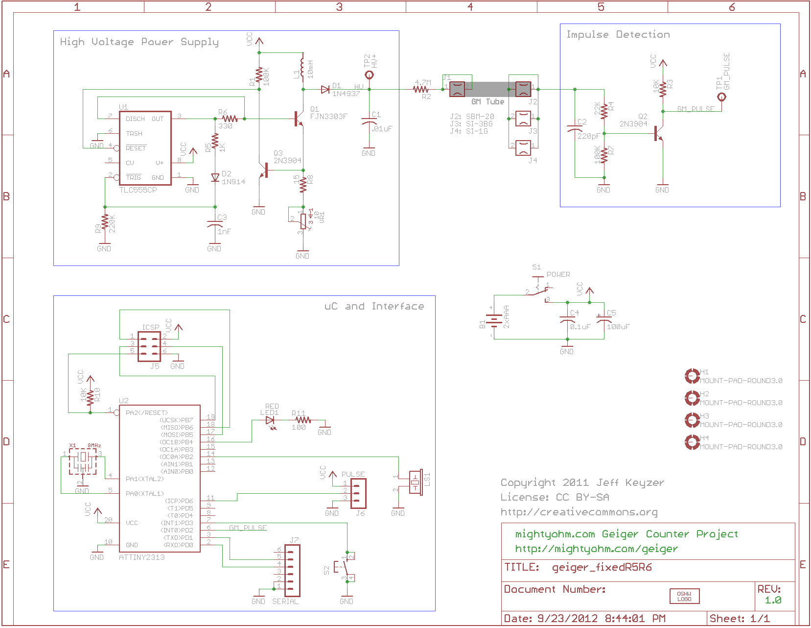
- the J6 Pulse header has ground (black triangle) marked incorrectly on the PCB
- the true pinout is the opposite direction indicated
- pin 1 with the black triangle is actually PULSE
- pin 3 at the corner is actually GND = ground
- the schematic diagram is also misleadingly labeled with ground on the bottom at pin 1
- I discovered all this when my rpi4 wouldn’t turn on and I started verifying connections with a multimeter and also by reading this comment, which turned out to be right
- The serial port readout is
/dev/ttyS0for the rpi4. It’s/dev/ttyAMA0for other rpi flavors - All the other instructions I found online are correct. I will summarize below
- Some multimeter meter fiddling leads me to believe the J5 ICSP header is also incorrectly labeled on the PCB, though I am not using this header for anything. J5 ground is on the bottom left, not the top right, when the the PCB is oriented with the headers facing down. The true location of ground seems to match the schematic
Intro
Everything about the
Banana Random Number Generator
resonnates with me. It has physics,
it has computer science,
it is DIY, and it is ridiculous. I’ve wanted to build it but
kids and life have prevented me from having hobbies…
Until now! N years later I’ve decided to try to do some Raspberry Pi’ing with a couple home DNS servers and separately re-learn soldering. I came across the Mightyohm Geiger counter and the planets and stars came into alignment.
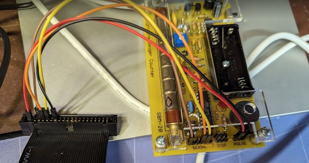
I cobbled together some 5-10 year old crumbs off the internet and after an hour or so I finally got a readout from the Geiger counter.
Here’s the recipe.
Materials
- Mightyohm Geiger counter
- Soldering equipment for the Geiger counter
- A Raspberry Pi 4
- I love the Canakit starter kit because it comes with a case, fan, heat sinks, micro SD card, micro SD card reader USB dongle for burning new OS images, power supply, and a power switch
- Don’t forget a mouse, keyboard, and optional HDMI monitor (unless you’re going headless). Get an RPi 400 to get mouse and keyboard bundled with the rpi4
- I have used and liked Amazon and Adafruit for rpi supplies
- Breadboarding jumper wires, especially female to female. I liked these.
Procedure
Assemble the Geiger counter
It’s fun and easy. I accidentally soldered my integrated circuit chips directly to the board! But it still worked. That ended up being the easiest thing to solder besides the header pins.
Connect the Geiger counter to the Raspberry Pi 4 GPIO
- Turn off the Raspberry Pi and unplug it.
- Turn off the Geiger counter and take out the batteries.
- Connect
- J6 PULSE pin 1 (incorrectly marked with the black triangle) to GPIO pin 1 3.3V
- J6 PULSE pin 3 to GPIO pin 14 GND
- J2 SERIAL pin 1 (correctly marked with the black triangle) to GPIO pin 6 GND
- J2 SERIAL pin 4 to GPIO pin 8 UART TXD (transmit)
- J2 SERIAL pin 5 to GPIO pin 10 UART RXD (receive)
Credit to this thread and this post for getting the pinout mostly right. Only one commenter on the first thread hinted at the incorrect PCB specification. The second post didn’t say anything about it (is this bug new?).
Turn on the Raspberry Pi 4 and read the data
Connect via VS Code
I like to connect to my rpi’s via VS Code.
- Add your rpi to
~/.ssh/config - Command-shift-p then “remote-ssh: connect to host” by name specified in your ssh config
- Enter password
- Command-shift-p then “view: toggle terminal” for a command shell
- Create an ssh key on your local computer with
cd ~/.ssh && ssg-keygen - Copy your public key to your rpi at
~/.ssh/authorized_keys
With the last 2 steps you don’t need to enter a password. My typical ssh config entry:
Enable serial comms (the UART pins)
This article was helpful.
- Log into your rpi.
- On your rpi, execute
sudo raspi-configin a shell. - Select “Interfacing Options”.
- Select “Serial”
- Set “login shell to be accessible over serial” to NO
- Set “make use of the Serial Port Hardware” to YES
- Exit the config and reboot (you will be prompted to reboot, otherwise do
sudo reboot)
Read the data
This entry
was great but not quite correct for rpi4.
Initializing serial.Serial to point to /dev/ttyS0 instead of /dev/ttyAMA0 works.
That’s it
Verify everything by running
python geiger.py
in an rpi shell and looking at the output in geiger.dat. Mine looks like
0 0 8 0.04
1 1 9 0.05
2 0 8 0.04
3 1 9 0.05
4 0 9 0.05
5 0 9 0.05
6 1 10 0.05
7 0 10 0.05
8 0 10 0.05
where the columns are count CPS CPM uSv/hr.
Comments